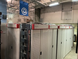
I am still recovering from the quite challenging logistical project of rescuing the Lucent 5ESS. This has been a whale of a project and I’m still in a state of disbelief that I’ve gotten to this point. Thanks to my wife, brother and some friends for their help, and to the University of Arizona, which has a very dedicated and professional information technology services staff.
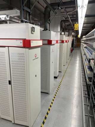
It started when I saw some telephone history enthusiasts posting about a construction bid at the University of Arizona. It turns out, the U of A had founded 5ESS in the late 1980s with a forward-thinking vision that established a phone system that would handle the university’s growth, phones that could be located anywhere with medium-speed data (ISDN BRI or PRI), and copper and fiber plants that would remain in use indefinitely.
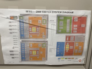
At its peak, it provided service on over 20,000 lines. He has written his own article ‘The End of an Era in Telecommunications’, which is worth reading. Notably, the machine had approximately 35 years of uptime, including two significant retrofits of new technology that resulted in the current Lucent-dressed 7 R/E configuration, which includes an optical packet-switched core called Communications Module 3 (CM3) or Global Messaging Server 3 (GMS3).
Moving 40 frames of equipment requires a lot of planning and hard work. The entire package takes two 26′ straight-up trucks, which is only 1′ shorter than a full standard American semi-trailer.
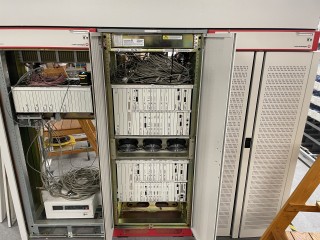
Coming from the world of computing and data networking, the creation of the switch was initially quite a surprise. It is physically composed of standard frames interconnected in rows opposite the datacenter equipment, but the frames are integrated into an overhead system for cable management. Internally, they are usually wired within the row and routed horizontally between multiple cable frames, but some connections have to transit above and across other rows.
Line trunk peripherals connect directly to a switching module controller (SMC) or an OXU (Optical Cross Connect Unit) that connects to an SMC and reduces the amount of copper cable going between lines. Alarm cables run directly to the OAU (Office Alarm Unit) or form rings between rows that ultimately terminate at the OAU. Optical connections go from the OXU to the SMC and then to the CM, with the copper test circuits running to the Home Metallic Test Service Unit shelf. Communications cables emerge from the top and run toward the wire frame, usually in large 128 wire cables but sometimes in smaller quantities for direct or cross connects of specialized services. A pair of Power Distribution Frames distribute -48V across the entire footprint, keeping redundancy at every level.
All it took was a cable tied together neatly with waxed string. Moving a single frame requires hundreds of different tasks ranging from quick to cutting cable laces to time-consuming removing copper connections and bolts in all directions.
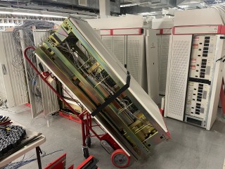
We were able to complete the removal in a five-day work week, and I was able to take it down to my receiving area in two days over the weekend where it now resides safely.
The next step will be to acquire some AC and DC power distribution equipment, which will have to wait until my funds recover.
I should be able to boot the Administrative Module (AM), a 3B21D computer, relatively soon by getting a small DC rectifier and this alone will be very interesting as it is the only use of the DMERT or UNIX-RTR operating system, which is a fault tolerant micro-kernel realtime UNIX from Bell Labs.
The system comes with a complete set of manuals and schematics that will be of great help in rewiring and reconfiguring the machine. Once the AM is on, I need to “de-grow” the disconnected devices and I will eventually add back an assortment of line, packet and service units so I can perform POTS as well as ISDN voice and data. In particular, I’m keen to interoperate with other communications and computing devices I have.
Due to power and space I will have to reduce the size of the system a bit so that I have spare parts to sell or trade.
Additional images are available here until I have a long term project page set up.
It’s a machine too big for one man, and it’s part of a broader project I’m working on to create a computing and telecommunications museum. If you are interested in working on the system with me, please feel free to contact me.
